Results
Movie
The movie window is divided into six parts. On the upper left you can see the sequence diagram with RF-pulse and gradient shape. At the lower left is the visualization of 3-D spin distribution and net-magnetization (red). On the right side from top to bottom, the transverse and longitudinal magnetization and phase are shown. There are two movies, the first one shows the first three echoes, and the second one shows the behavior in steady state.
Spoiling
The goal is to completely destroy the transversal magnetization Mxy. We call this ideal case "perfect spoiling" and simulate it by setting the Mx- and My- components to zero at the end of each TR. Figure 3 shows that the transverse magnetization in steady-state is not zero after the gradient (red curve). In the lower picture you can see, that RF-spoiling with dedicated phase(-increment) is much closer to the ideal case.

Figure 3: Transverse magnetization in steady-state (SS_spoiling_mxy.jpg & SS_spoiling_mxy_zoom.jpg)
T1 contrast
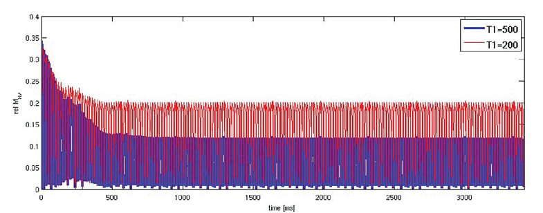
As mentioned in the introduction the FLASH-sequence is used if a T1-contrast is needed. In figure 4 it is shown that the signal intensity depends on T1. The longer T1, the less the longitudinal magnetization and the transverse component after the RF-pulse (the transverse component before RF is spoiled and the transverse magnetization after the RF-pulse depends only on a longitudinal component after spoiling).

Figure 4: T1-contrast: signal intensity depends on T1.
Phase increment (best increment)
Every spin in our simulation has a position-dependent resonance offset (due to the spoiler gradient). To this offset a position-independent but linearly increasing RF-pulse number-dependent phase ![]() is added during each precession period. In order to find the optimum value of
is added during each precession period. In order to find the optimum value of ![]() , the steady-state signal was calculated as a function of
, the steady-state signal was calculated as a function of ![]() , which can be seen in figure 5.
, which can be seen in figure 5.

Figure 5: Transverse magnetization in steady-state as function of RF phase increment. (phase_inc20.jpg)
Peaks in the amplitude of the signal are observed for certain values of the phase increment. These peaks occur when ![]() is equal to 360/m [Crawley et al(10) and Sekihara (19)], where m is an integer, as a result of incomplete cancellation of transverse magnetization prior to each RF-pulse. The dashed line in figure 5 corresponds to the ideal FLASH signal. It can be seen, that the calculated signal is very close to the 'perfect spoiled' signal, when
is equal to 360/m [Crawley et al(10) and Sekihara (19)], where m is an integer, as a result of incomplete cancellation of transverse magnetization prior to each RF-pulse. The dashed line in figure 5 corresponds to the ideal FLASH signal. It can be seen, that the calculated signal is very close to the 'perfect spoiled' signal, when ![]() or
or ![]() .
.
Optimal flip angle (Ernst angle)
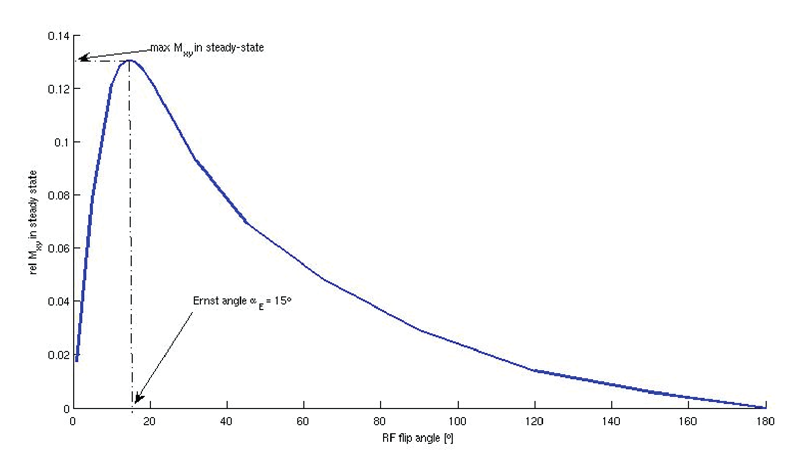
Figure 6 shows the dependence of the transverse magnetization on the flip angle a with respect to relaxation time T1 and repetition time TR. It corresponds to the dependence of the longitudinal magnetization on the flip angle.

The flip angle that provides the optimal resulting Mz magnetization can be calculated via the ERNST-equation:
![]() .
.
In this case a TR of 17ms and a T1 of 500ms has been used.
References:
[1] Zur Y. et al. "Spoiling of Transverse Magnetization in Steady-State Sequences", MRM 21, 251-263 (1991)
[2] Hargreaves B. http://mrsrl.stanford.edu/~brian/bloch/
[3] Haacke E.M. et al."MRI - Physical Principles and Sequence Design", Wiley-Liss (1999)
[4] A.P.Crawley, et al., Magn.Reson.Med. 8, 248 (1988)
[5] K.Sekihara, IEEE Trans. Med. Reson. 71, 212 (1987)
| By André Viklenko / Sebastian Wolf |
